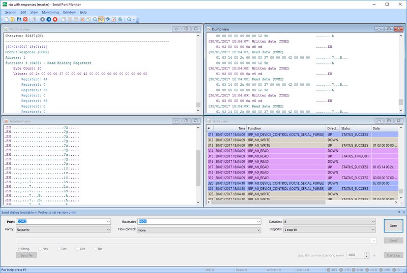
Use the Serial Port Tester
Once the settings are in order you can begin a new testing session by following these steps.
1. Launch Serial Port Tester
2. Choose “Session >>> New session” from the main menu. You can also use the keyboard shortcut “CTRL+N” or click “New” on the main toolbar.

3. The “New monitoring session” window will be displayed.

- Line view displays detailed information about the requests that are sent on a specific serial line.
- Table view presents the recorded IRPs in table format.
- Terminal view presents the received data in a text console of ASCII characters.
- Modbus view displays received and sent Modbus data (RTU and ASCII).
- Dump view displays all sent and received data transmitted through a serial line.
The checkboxes designated as “Start monitoring now” and “Start in new window” control how the new monitoring session is initiated.
Capture options: select the options you wish to monitor from among – Create/Close, Read/Write, and Device Control.
When you are finished setting the options, activate the new session by clicking the “Start monitoring” button.
4. The new monitoring window is displayed containing the selected visualizers.

5. Save a session by selecting “Session >>> Save session/Save session As” from the main menu. You can also click “Save” on the main toolbar or use the CTRL+S keyboard shortcut.

6. When prompted, select a file name. Use this file to reload the session at a later time to continue the working with it.
Check the COM port due to loopback test
What Is A Loopback Test? A Loopback test involves transferring data back and forth from only one COM port. A COM port loopback test occurs when an original signal has been initiated from a specific device and then returns to the same device which the signal originally emanated from (aka, the loopback).
What Information Does The Loopback Test Provide?
Performing a serial port loopback test verifies the operation of serial communication as data is sent and received via the same Serial Port.
With the help of a serial loopback test software, users can identify problems in their serial port, cable connection, or the software that generates the messages without needing to connect with third-party hardware.
The use of loopback tests is to confirm proper RS232, RS422, and RS485 serial communications.
To perform an RS232 loopback test: the first step is to assure that the “TXD pins” and “RXD pins” are connected.
The RS232 Loopback Test allows users to transfer data from the Transmission Conclusions to the Reception Conclusions. Due to the correction being differential in regards to RS422 and RS485, the “TXD +” should connect to “RXD +”, while the “TXD -” is connected to “RXD -” contacts.
To perform a more sophisticated loopback test that permits hardware flow control capabilities requires more contacts to be connected. More connected contacts would then allow the flow control signals to transmit correctly.
As an example, when carrying out the loopback test RS232, the “CTS pins” and “RTS pins” must be connected, as well as the “DTR pins” and “DSR pins”.
For RS422 and RS485, “CTS +” must be connected to “RTS +”, and “CTS -” must be connected to “RTS -”.
Loopback Testing Using The HyperTerminal Utility
For users wanting a more convenient way to perform a loopback test, they can put to use the HyperTerminal utility.
The use of HyperTerminal means that a user’s computer will act as a terminal, itself. This allows it to connect remotely with other systems.
HyperTerminal employs Telnet, or a standard RS232 serial bus, to connect with remote devices.
Because HyperTerminal utilizes serial ports for data transfer, it can be used effectively when running loopback testing.
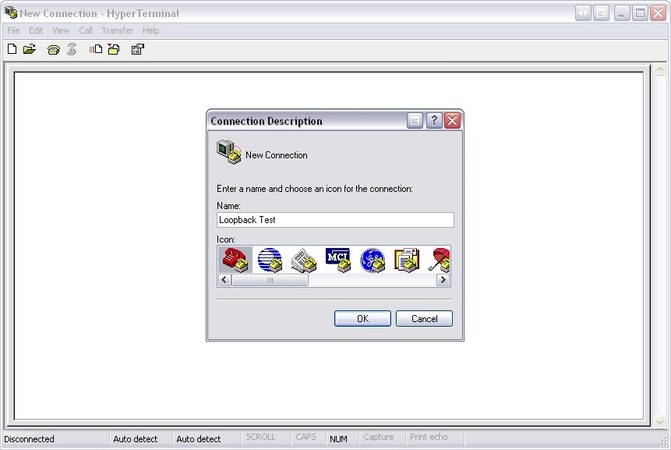
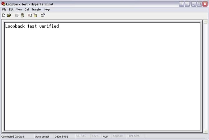
Begin by creating a new connection. For the purpose of this example, we have named the connection “Loopback Test”, but connection name and icon choices are up to the user’s preference.
Once a name and icon have been chosen, click “OK”.
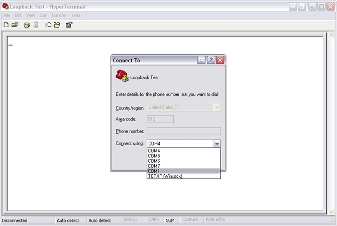
Select the communication port you would like to check.
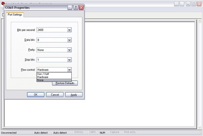
Then select the flow control type that you would like to use. Note that Xon / Xoff is a unique flow control Serial Loopback Test software, and only requires the connection of “TXD pins” and “RXD pins”.
Once flow control is selected, enter the message using your computer keyboard. Any data displayed in HyperTerminal comes from the device you have just run the loopback test upon.
Check the Cabling
When using a DTE instrument you may need to employ a null-modem adapter to test COM ports. You can also try to rewire the cable connector if you are feeling adventurous.
- The first wires to connect are the ground, RXD, and TXD.
- Using the device’s documentation, attempt to identify the signal wire that carries output data and connect this with the computer’s RXD.
- The computer’s TXD needs to be connected to the signal that carries input data to the device. Be careful not to rely solely on the signals’ labels. The same signal can be an input or an output based on the type of device being used, for example, a computer or a modem.
It can be challenging to determine which type of device you are handling. Documentation often skips over this information, but you may be able to deduce it from some of the device’s other signals. Modem type devices will have DSR as an output with a counter using DTR as its output. Knowing a single signal’s direction allows you to figure out the rest of them. Some manufacturers reverse the labeling of data signals for modem types of equipment, so proceed carefully.
With correctly named signals you have:
- a computer to computer link which connects TXD to RXD and RXD to TXD.
- a computer to modem link connecting TXD to TXD and RXD to RXD.
Crossing connections in this way is known as a null-modem arrangement and you may need to buy an adapter to replicate this connection to conduct your COM port test.
Set Handshaking or Flow Control
Set Hardware Handshaking
Once you have correctly wired the signals you should be able to conduct your serial port test. If messages are still not getting through, tying the handshake lines might do the trick.
There are two reasons for using a handshake arrangement.
- A computer that is not ready to receive data can stop a device from sending any.
- A device can prevent data being sent from a computer if it is not ready to receive it.
Just because your device has the inputs and outputs which make it capable of handshaking does not mean that you have to implement it. Many manufacturers just put the signals on the plug since they are available from the device’s processor. Your best bet regarding handshaking is to begin by connecting possible handshake lines with fixed voltages. In this way, they won’t impact the device’s operation. You will find that many devices already have resistors tied to handshake lines. This enables you to not connect them if you don't need handshaking.
If no handshaking is implemented when you start to test a serial port, what indications will you get that suggest it may be required?
- One indication that handshaking is needed is if the input buffers overflow causing the computer to miss part of the sent message.
- A device may also miss a portion of messages sent by the computer which will negatively impact its operation.
If you need to use handshaking with the serial port test software, be advised that Serial Port Tester employs DTR / CTS handshaking. In this configuration, the computer will use its DTR output as a sign that it is ready to receive data. The CTS input is available to be controlled by a device to limit the computer’s ability to transmit data. The status of the CTS input on the computer is only relevant when hardware handshaking is enabled. With no hardware handshaking, this input is ignored, but the DTR output is kept at a high level so it can be used to tie unused inputs to your device.
In some cases you will want the DTR to be low and the RTS to be high. To accomplish this, the handshaking needs to be removed.
- Connect pins 8 and 7 (i.e. CTS drives RTS).
- Connect pins 1, 4, and 6. This should maintain the DTR line in the correct state, by connecting it to DCD and DSR.
This modification is usually made at the device side instead of the computer’s end of the cable. Make sure that data transmission and reception is still occurring on the cable.
Set Software Handshaking
Xon \ Xoff Handshaking is a software protocol that can be used to control data flow. Here’s how it works. When a computer is sending data to a device, the device sends a single Xoff character when it cannot accept any more data at the moment. This stops transmission, which will commence when an Xon character is received by the computer, signaling to restart the communication. Either the device or computer can send the Xoff and Xon character. You can select this type of handshaking in
COM Port Tester if your device requires it.
Return to the Serial Port Tester
After you have resolved any issues by going through the steps outlined above, go back to step one and check the COM port lines status.

Below the main table, the states of the serial control lines are displayed.
- RTS : Request to Send line indicator
- CTS : Clear to Send line indicator
- DSR : Data Send Ready line indicator
- DCD : Data Carrier Detect line indicator
- DTR : Data Terminal Ready line indicator
- RI : Ring line indicator
The color of the circles indicates the state of a particular line with green indicating a high level, red standing for a low level, and gray for an undetermined state.
Serial communication issues can be hard to diagnose and correct. There are several strategies that you can try, and we have discussed some of the more common methods. RS232 test software can be an invaluable tool in fixing your serial communication issues. Serial Port Tester from Electronic Team is an excellent solution. It is a flexible and versatile tool that provides the user with an advanced set of features. If you test or develop serial devices and applications, this tool should be in your software toolbox.


