Cookie
Electronic Team, Inc. uses cookies to personalize your experience on our website. By continuing to use this site, you agree to our cookie policy. Click here to learn more.

Serial data logger. Software for monitoring and logging COM port data

Try Serial Port Logger now
14-day free trial


Serial ports are used to connect computers with many types of scientific and industrial devices. Using a machine’s COM port you can capture the data transmission and display it in spreadsheets, databases, and other types of analysis software.

Monitoring and analyzing serial communication requires the use of a serial data logger. This specialized software reads and displays RS232 data and can save it to a file so it can be analyzed at a later time.

You need serial data logger software that can interact with a computer’s COM ports to collect the transmitted data. The best choice in this kind of software is Serial Port Logger. It offers a fast and easy method of displaying serial port activity and recording it to a file.

In this article, we will look at how to use Serial data Logger Software to monitor and log your serial port data.

Table of contents:

  1. COM port logger settings
  2. Step-by-step guide to RS232 data logger software
  3. Conclusion


Serial Port Logger

COM Port Logger is an innovative software that allows you to capture serial port data and track all port activity from the software’s logs.
Serial Port Monitor logo
Serial Port Monitor
Log and analyze serial port activity
4.8 Rank based on 345+ users, Reviews(345)
Download 14-day fully-functional trial period
Serial Port Monitor

COM port logger settings


The first thing that needs to be done is to set the communication parameters in the software to conform to those being used by the serial device. We are talking about the COM port number, parity, data and stop bits, and the baud rate.

COM Port status bar

COM Port Number


The COM port that will be used by the RS232 data logger needs to be specified. Your computer may have more than one COM port. It might also not have any serial interfaces. If that is the case, you can add more using hardware converters, software or software solutions depending on the communication options available on the computer. Select a converter that works with your machine whether through the Ethernet, Bluetooth or USB. For information on using USB converters check out Tips on Using USB-to-Serial Converters.

Baud Rate


Data transmission through COM ports employs serial communications where messages are sent one bit at a time in a sequential manner. The baud rate describes the maximum speed of data transmission. Both the COM device and the computer must use the same baud rate to enact serial communication. Select the baud rate that conforms to your device when setting the parameter in the data logger software application. A faster baud rate reduces the time required to send and receive messages, and you should select a high value if your device offers that option. If you are connecting over long distances or you find the communication is unreliable, you may need to lower the baud rate.

Regardless of the connection speed, the RS232 port logger will determine how fast you can capture information about the transmission.

Data Bits


A serial port receives data one bit at a time but processes it in groups of seven or eight bits. It’s critical when using a serial port data logger that the software and device group the received data in the same way. The device’s user manual should indicate the number of data bits that it uses. When in doubt, use eight data bits in the RS232 logger as this is the more commonly used setting.

Parity


Parity defines whenever an entity is odd or even. It can be used for error checking in serial communication. When parity checking is enforced, the number of 1’s in a group of data bits being sent is counted. The device or computer determines if there is an odd or even number of 1’s and sets the parity bit based on that information. When the data is received the same procedure is used to verify if the value of the Parity Bit agrees with the one which was sent.

A parity check implies that the computer and serial device use the same method when calculating the value of the Parity Bit. Parity can be set to on for either an odd or even number of 1’s in the transmission. Both sides of the checking equation must set the value in the same way. Using Even Parity sets the Parity Bit to one when an even number of 1’s are involved, with an Odd Parity value of one indicating an odd number of 1’s have been sent.

Parity checking provides a basic and limited form of error checking. While it will alert you to an error of a single bit, this type of error checking will not help if two bits were affected. No information concerning which bit is in error is supplied. There are other error checking techniques such as cyclic redundancy checks or employing the Start and Stop bits.

Parity can be set to “None” and should be done so in the COM port logger if you cannot determine the parity settings of the device.

Start and Stop Bits


Asynchronous communication is used in RS232 ports, meaning that data transmissions are sporadic and are not constrained by set time intervals. This requires that a device has the capability to identify the start and end of a message. Start and Stop bits are used for this purpose. The Start Bit is sent before any of the data bits and the Stop Bit is appended after the data bits or the Parity Bit if it is in use.

Data lines can be in the on or off state. Idle lines are considered to be on. The line is set to off by an instrument or computer when it is preparing to send data. This is the Start Bit and is immediately followed by the data bits that comprise the message.

The Stop Bit is used to enable a computer and device to sync with each other if an error, such as noise on the line, interrupts the transmission. The baud rate and the number of data and parity bits are used to calculate the time interval between the Start and Stop Bits. Stop Bits are always on, so if an off value is detected at the receiving end it indicates that an error has been encountered.

Though the term Stop Bit is used, the entity is not a physical bit. It is a value that indicates the minimum length of time a line must be on when data transmission is complete. On PCs it is usually either 1 or 2 bits which is specified in the driver parameters. The most commonly used value is 1 and your message may be slower when using a value of 2. If the number of data bits is less than 7 you may see a Stop Bit of 1.5. ASCII characters cannot be transmitted with 7 bits so this setting is rarely used.

Flow Control (Handshaking)


When you first connect a device to a computer you should try it without using flow control. Flow control may be needed if you find the device is missing parts of messages which can cause it to fail or work incorrectly.

If you need to implement flow control it will most often be an Xon \ Xoff (software) selection. You can learn more about handshaking in our manual of testing serial port.

Serial Data Logger quick user guide


After configuring the RS232 data logger software setting, you are ready to use it to monitor the serial port traffic on your system. The following steps outline the process.

1. Download and install the serial data logger program and start the application.

Select the “Session >>> New session” option from the app’s main menu. You can also click “New” on the main toolbar or use the CTRL+N shortcut when starting a session.

New session

3. You will be presented with the “New monitoring session” window.

New monitoring session

This is where you can select which visualizers are used for the session. They control how the data is displayed. You can choose any number of visualizers by checking the box to the left of its name.

  • Table view uses a table format to display recorded IRPs.
  • Line view provides detailed data transfer information regarding a designated serial line.
  • Dump view shows all of the data that was sent and received through a serial line.
  • Terminal view displays data transfer information on a console in ASCII format.
  • Modbus view displays any Modbus data (RTU and ASCII) sent or received in the session.

Characteristics of a new monitoring system are set by selecting either the “Start monitoring now” or “Start in new window” checkboxes.

You can control which events will be monitored during the session by selecting Read/Write, Create/Close or Device Control.

4. Click “Start monitoring” when you are finished tailoring the settings to begin the new session.

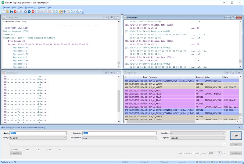
The program will open a new monitoring window which will present the serial data in the formats chosen when selecting visualizers.

The monitoring window

5. Sessions can be saved by selecting the “Session -> Save session/Save session As” option on the main menu. Alternately, you can use the CTRL+S keyboard shortcut or choose the “Save” button located on the main toolbar.

Save session
Try COM Port Logger now
14-day free trial

Conclusion


RS232 Data Logger is a professional utility that enables you to easily monitor and save serial communication data for immediate use or later analysis. Its settings are fully customizable, allowing you to use the application with any serial device or interface. Its a great tool for individuals who work with serial devices or applications.

small logo Serial Port Monitor
#1 at Serial Port Software
Serial Port Monitor
Log and analyze serial port activity
4.8 rank based on 345+ users (Learn more)
Get a download link for your desktop
Submit your email address to get a link for quick download on your desktop and get started!
or